Photos from the disassembling of the laptop are pictured below.

The removal of the hard drive and battery.
 |
The hard drive of the computer
|

The cover of the RAM on the computer.

The bottom side of the RAM of the computer.

The top side of the RAM of the computer.

The slot in the computer which houses the RAM.

The top plate of the computer without the keyboard attached.

The keyboard input peripheral removed from the laptop base. The tab which connects it to the laptop for input capabilities can be seen toward the bottom of the photo.

The plate which contains the power button as well as volume control.

The series of resistors, capacitors, and transistors beneath the power button and volume control.
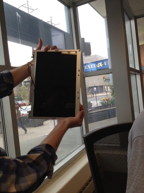
The screen removed from the laptop base.

The interior of the computer, featuring the motherboard.

A less zoomed image revealing the totality of the interior of the computer.

SCREWS FOR DAAYYYZZZ!
A pan over the interior of the laptop with a brief description of the heat sink and some colorful commentary. Pardon the bizarre voices!
No comments:
Post a Comment